Oil on Water Detection by using UV- stimulated Fluorescence
Task definition
Fluorescence Oil Detection
According to the national and international environmental laws concerning water
“every person is liable for taking the necessary precautions, according to the specific conditions, to prevent oil pollution of water”
It is very important that water of industrial plants never introduces oil into the process or into the environment. For this reason, a continuous monitoring of water is necessary at the outlet of those plants, where oil emissions are possible in case of operational malfunctions. The problem is, that produced water carries typically a considerable load of contaminations, e.g. sand, mud, algae or salts. Operation conditions such as temperature, speed of flow or water level are not constant. These changing process properties make it very difficult to get reliable oil monitoring results.
Measurig of the absolute oil amount in mg/l or ppm is not really possible by using the known inline & online measuring systems. Reasoning for this statement is, that oil is not homogeneous distributed in the water. The systems capture only a fraction of the total water quantity for analysis. The biggest quantity of the water is not measured, at installations in open channel, basin, tank or large pipes. Taking a representative sample with average oil content is virtually impossible, because the distribution of the oil fluctuates unpredictably within the water.
Parameter like water depth, temperature, speed of flow and oil type affect the oil distribution in water.
As an example:
Very often you will find no oil in a water depth of 30cm, but there is an oil film on the water surface. Almost all types of oil or at least their components are lighter than water and therefore they float. Due to this property we can expect to get the highest oil concentration at the surface or in the upper region of large pipelines. The oil monitor model FLUCOmat uses the floating characteristic of oil to ensure maximum sensitivity.
Overview of different measurement methods
Various methods are used to detect oil in water:
- UV- stimulated fluorescence oil detection
- IR- reflection
- Absorption photometry
- Conductivity measurements at the water surface
- Capacitive measurements
- Transfer of oil in a solvent for hydrocarbons & spectroscopic analysis of the solvent
- Light scattering turbidity metry
- Transfer oil hydrocarbons to gas phase (e.g. stripping with air) and their detection into the gas phase (e.g. with a FID)
Most applications concern water that contains contaminants as like sand, salts, algae, mud, etc. beside the oil. These particles can considerably falsity the measurements. Methods requiring contact with the fluid, e.g. flow cells or dipping electrodes in the fluid, may be disturbed in their function by the following influences:
- Floating dirt
- Growth of algae
- Variations of the surface e.g. waves, position, etc.)
- Oil coating of sight glasses
- Contamination of flow cells
- etc.
Much maintenance is needed, to ensure the reliability of such instruments. Measurements based on sampling of the fluid have problems with oil and dirt covering. Due to the difficulties with these measuring methods, it was sense full to develop a non contact monitoring method. Since the oil usually floats we developed the idea of a sensor positioned above the water level. The detection should be done by using a suitable radiation method. Such a method is the surface detection of the electromagnetic rays caused by UV- stimulated fluorescence. Thin oil films on a water surface result in interference pattern easily recognized by the human eye.
The fluorescence method is by far more sensitive as the human eye and allows detecting oil layers of less than 3µm. The model FLUCOmat uses these methods and provides highly sensitive and reproducible monitoring results paired with low maintenance.
Measuring Method of UV- stimulated Fluorescenc
Principle Fluorescence Oil Detection:
- UV-Radiation stimulates the oil to fluorescence
- a highly sensitive photomultiplier recognizes the oil’s fluorescence
- the field transmitter converts the detector signals into measuring results
Radiant energy (E1 = h1) in the ultraviolet, can be absorbed by an atom or molecule, thus exciting electrons to a higher level of energy. Falling back to the ground state, the electrons emit a radiation (E2 = h2), with a higher wavelength as before absorption. The rest of the energy is emitted by the system in other forms, e.g. as kinetic energy (thermal radiation) (E3)
E1 = E2 + E3
The emitted wavelength (fluorescence radiation) is specific for the monitored oil. Sensitivity and selectivity can be influenced through selection of excitation and detection wavelength. The fluorescence detection method described here, has a sensitivity of one droplet (approx. 0,1ml) per m2 surface. However, this depends on the process conditions and on the installation of the system (flow rate, waves, distance from the surface, speed of flow, etc.).
Even this method can be affected by:
- ambient light with extreme high intensity
- Large waves
- Strong movement of the surface (waves, variations in water level, etc.)
- Swimming debris at the surface
The technical conception of model FLUCOmat and a well chosen measuring location minimize these effects.
Technical Realization Fluorescence Oil Detection
The instrument is designed for continuous operation in industrial environments, a low maintenance requirement is guaranteed. The influences due to external disturbances are minimized.
Model FLUCOmat (FLU-103) UV- Emitter:
To stimulate the fluorescence, UV- lamps or optional UV- LED arrays are taken as UVSources. These UV- Sources are arranged above the detector optic and cover a detection area of about 30cm diameter. This design allow detecting even from moving water surfaces, the sensitivity is not reduced by waves up to 3cm.
Model FLUCOmat (FLU-103) Detector Optic:
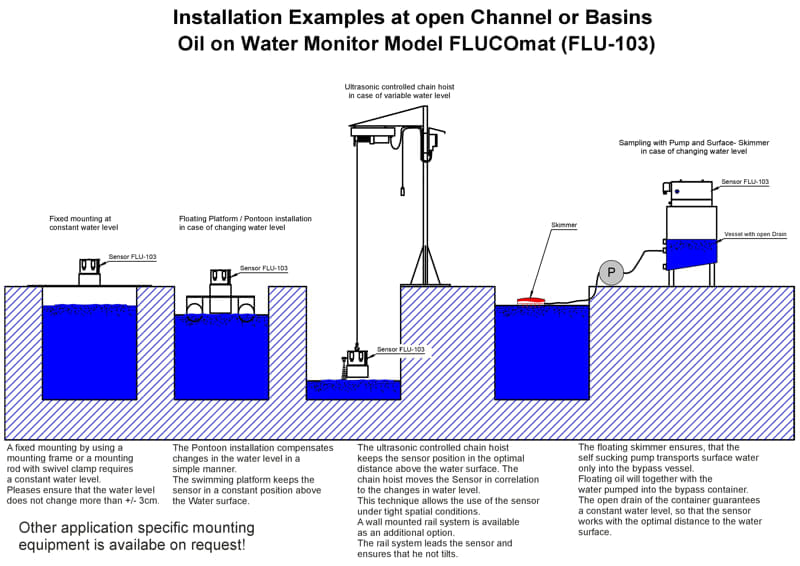
The receiver optic is adjusted for a distance of about 400mm instrument sensor and water surface. Variations of the distance (e.g. changes in water level) more than 75mm should be compensated by a suitable installation (e.g. installation at pontoons, using of an ultra sonic controlled lift system, bypass container, etc.).
Model FLUCOmat (FLU-103) Signal Pocessing:
A stability controlled Photomultiplier is used to recognize the fluorescence radiation. The modulation of the UV- Sources compensates for ambient light by demodulation of the receiving signals (see fig. 1)
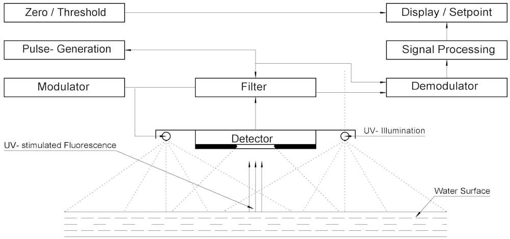
Figure 1: Operating Principle of the Oil Monitoring System Model FLUCOmat
Model FLUCOmat (FLU-103) Status Signals
The correct functioning of the system is guaranteed by permanent self monitoring of the following parameter:
- UV intensity of each UV- source
- Modulation / Demodulation
- Sensitivity of Photomultiplier
- Power Supply
Malfunction warnings are displayed by four LED’s. A common relay is configured to transmit a failure or a malfunction warning to the control room.
An isolated analog output (4-20mA) transfers the monitoring results to a control room.
Operating Experiences Fluorescence Oil Detection
Model FLUCOmat (FLU-103) Results of a Laboratory setup:
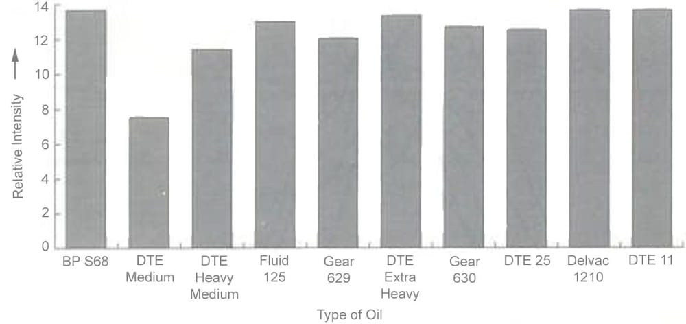
Bild 2, zeigt die Empfindlichkeit für mehrere Öle, die unter Verwendung eines Laboraufbaus nachgewiesen wurden.
The FLUCOmat (FLU-103) model is already in use for many applications:
- Oil in drinking water reservoirs
- Turbine oil in power stations
- Hydraulic oil
- Oil in cooling water
- Heat exchanger oil
- Oil in production water
- Oil in retention basins
- Direct discharge into rivers / lakes
- Discharge to public wastewater systems
- Water flow from turbines
- Water from various collectors
Rainwater
.